Original post: http://www.mk3supra.org/topic/9-guide-changing-capacitors-on-a-1jz-ecu/
The 1JZ has some issues with electrolytic capacitors (known as ‘caps’), five to be precise. This is not unique to the 1J, several other ECUs are known to suffer quite badly from a similar ill including MR2s and GTOs. As it happens, a heck of a lot of cars have a very similar set up but for whatever reason the 1J has issues.
OK so symptoms? All sorts! Sometimes it is not starting, sometimes idling issues, some time cutting out etc etc. Needless to say with a component that ages and a car that has aged it is worth having a check on these every few years like any other service item. The downside is that when they let go they can (and usually do) cause a lot of damage. This includes destroying the PCB (printed circuit board) and eating the copper tracks that are essential for circuits to be connected.
The good news is that you don’t have to be an electronics expert to deal with this but you need to follow some precautions. If you know someone who is a whizz with a soldering iron then rope them in to help you, if not then get practicing before you attack the PCB!
Step 1 – Remove the ECU from the car, see the 7M guide for fitting a turbo timer (step 42 to 51)
Step 2 – Remove the 4 screws holding the outer cover in place
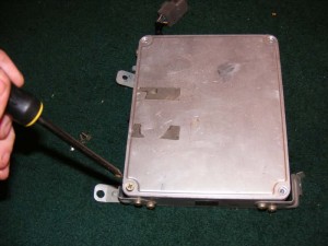
Step 3 – Remove the cover to expose the PCB. Note that as soon as you are working with electronics like this you should be in an ESD (electro static discharge) safe environment. If you don’t know about this then you probably shouldn’t be working on the ECU.
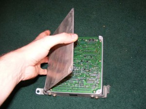
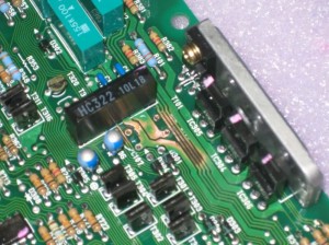
Step 4 – Have a look across the PCB for any signs of damage. On mine, the 5 capacitors very quickly revealed themselves as shown
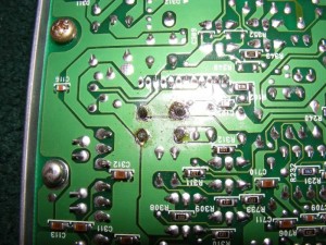
Step 5 – Now remove the 6 screws holding the board to the metal frame

Step 6 – Two more screws hold one of the mounting brackets on, remove these to gain access to the screw running down the side of the ECU
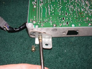
Step 7 – Remove the 4 screws running along the edge of the ECU (note you pull back a sticker to find one)
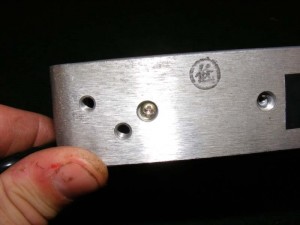
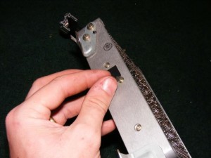

Step 8 – Now flip the ECU over to gain access to the other side – obviously be aware you have a bare PCB exposed now
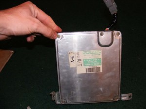
Step 9 – Remove the 5 screws holding the outer cover on (extra one for clamping the wiring loom in place)
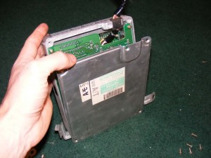
Step 10 – You now expose the second board. Note that I had a wire link mod (the yellow wire) which was someone’s previous attempt to fix the capacitors, you shouldn’t see this
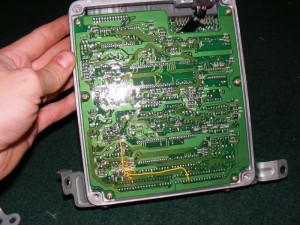
Step 11 – Another 6 screws will release this second pcb
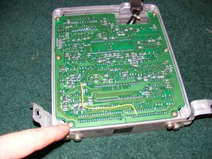
Step 12 – Slide the rubber cable gland out of its recess
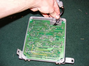
Step 13 – Now ease the top board towards you, note the connector for the EUC points away from you as the board comes up
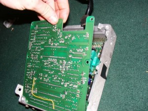
Step 14 – Two ribbon cables join the two boards together so be gentle when moving the assembly around
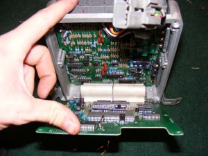
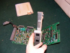
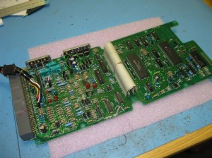
Step 15 – Lay one board flat down on the ESD surface (it might look like a carpet to you … do as I say not as I do!!) as shown in picture 1. Then drop the other side away gently too (picture 2) before twisting the boards and easing them out of the metalwork (picture 3).
Take your time and DO NOT force the boards out, they will slide out when you get them angled correctly

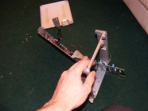
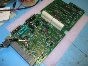
Step 16 – With the boards out you can start to really assess them and look for dry joints, bad tracks, the 5 capacitors etc.

Step 17 – Capacitors – they look like this. It’s a reasonably tall component, cylindrical and has two legs (positive and negative). Their value is measured in ‘farads’ and you get farads, millifarads, microfarads and picofarads typically.
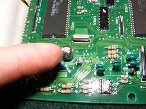
Contrary to what some people think, the 5 components are actually very high end components with really good specifications for tolerances and life. I have downloaded the datasheet in case this link ever fails but you can find the specs of the PW series Nichicon here :
http://www.nichicon.co.jp/english/products/pdf/e-pw.pdf
Replacing with standard parts is not a bad idea if you can get them.
Step 18 – Circled in this drawing are the 5 capacitors you need to change
Capacitors and their values:
1 – 47uF
2 – 33uF
3 – 220uF
4 – 100uF
5 – 15uF
Check RS or Farnell to find alternatives for them all. I went for the following:
1 – 47uF Nichicon UPM1J470MPD 63V (18 pence each, minimum order quantity 5)
2 – 33uF Panasonic EEUFC1H330 50V (13 pence each, minimum order quantity 5)
3 – 220uF Panasonic EEUFM1H221 50V (33 pence each, minimum order quantity 1)
4 – 100uF Panasonic EEUFM1H101 50V (17 pence each, minimum order quantity 1)
5 – 15uF Sanyo Os-con 25SH15M 25V (115 pence each, minimum order quantity 5)
The 15uF is the awkward one, I had to get a 25V range which should be absolutely fine. It’s better than having to parallel up 10uF and 4.7uF imo. Total cost <£10 and you have a load of spares too!
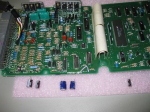
Step 19 – Use a desoldering station to melt the solder on the legs of the capacitors and suck it away. If you can’t gain access to one, use a ‘solder sucker’ which is available from the likes of Maplin for a few pounds.
If you struggle to get the solder to melt well then ADD a little more and it will help it flow better.
NOTE: Make sure you refit the capacitors in the correct orientation! They ARE polarity sensitive i.e. negative and positive matters! On the plus side, they all face the same way with the negative leg (the short one with the line on side of the cap) facing towards the multi pin connector when laid out as shown in picture 18

Step 20 – Remove all 5 caps from the board
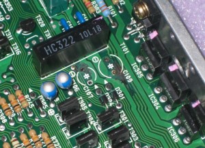
Step 21 – Check around the board to see if there are signs of corrosion or damage to the tracks. I had problems with C107 and C109 (these identifiers are printed on the ‘silk screen’ i.e. the white text on the PCB). The cause of corrosion on my ECU is likely to have been flux residue from a previous repair of the capacitors – cleaning the board is essential after performing work like this, don’t forget!
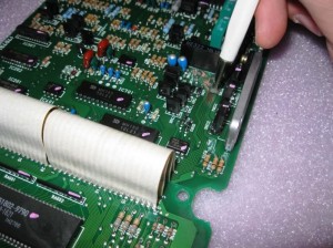
Step 22 – To remove the corrosion, flux residue (used in the soldering process) and the tarnished solder-resist (green bits on the PCB), a fibreglass brush is used. This is something you should go out and buy, don’t use sandpaper etc, this is delicate work to expose the copper track underneath the thin layers.
You can see in the picture the brush being used to expose the copper
Step 23 – This picture shows the area cleaned up – note that the copper has been ‘eaten’ in the circled area rather than being a smooth radius. this was the start of some bad news!
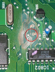
Step 24 – It’s very important you identify any breaks in tracks, one is highlighted here in this picture. These need to be repaired by either wire linking either side of the break or by repairing the track. Repairing is pretty much same as the wire link ‘bridge’ but you lay wire across the lines of the existing track and solder across it. To do a good repair takes quite a bit of skill, I know my limits and got an engineer on mine – see picture 2 for results
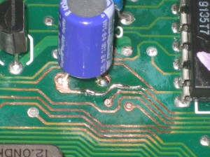
Step 25 – Solder in the new caps, pay attention to the markings to make sure they all face the same way! The negative has the short wire and there is normally a line running down this side of the capacitor.
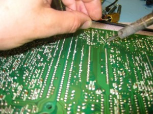
Step 26 – Once all 5 caps are in, check over everything and make sure you have thoroughly cleaned around any areas that you have soldered with a suitable PCB cleaner
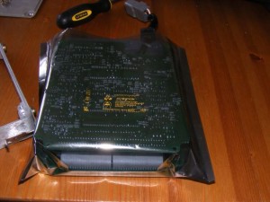
Step 27 – I had to transport the PCB to and from work so make sure you have access to ESD bags as shown if you are doing this, the last thing you need to do is zap the board after you’ve repaired all the caps!
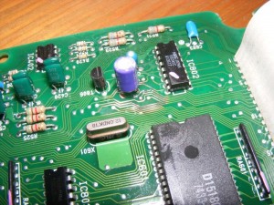
Step 28 – Make sure you re-coat the board with a protective laminate layer, this is a special varnish known as conformal coating. You can use any kind of conformal coating you like but do protect the board. I tried to show the coating in the picture but you can’t really see it. I suggest you brush it on as opposed to spray unless you want to make up templates etc
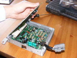
Step 29 – Wriggle the PCBs back into their frame again
Step 30 – Refit the 6 screws to either board then the 4 screws down the side and the 4/5 cover screws (see steps 2-11 if you forgot!)

All done, it’s not too difficult but you could do with having some reasonable kit to do a good job, at the very least:
1. A good soldering iron
2. Fibreglass brush
3. Conformal coating
4. An ESD mat
Additional info:
I must add some. In the past, I have fixed different ECUs and what I can say is that you have to be very careful for selecting the electrolytic capacitors. The internal impedance or the ESR is the key to select. The capacitance value was not very strict. Sometimes +200% did not cause any problem. For an example, I have used 100uF instead of 47uF and it was fully OK. But when I have used a regular type of capacitor, it did not fix some problem.
When you replace them, if you make sure they’re the 105 degree rated caps, they’ll last MUCH longer than the usual 80~ish degree rated caps.
Those who could not succeed or who are about to fix the ECU, I suggest you to use low ESR type capacitors such as Rubycon type ZLH, Nippon Chemicon KZH, Panasonic EEU and other equivalents.
Using Rubycon ZL or YXF series, Nichicon HE, or Panasonic FC series will work fine. Preference basically in that order.
The actual ripple and ESR values aren’t that important, just choose caps with the highest ratings you can get.
ESR (Equivalent Series Resistance)
Suggested Places to get caps from…
15uF 35V (15uF 63V, 491-0412, RS)
Nichicon HE – UHE1J150MDD – http://lt.farnell.com/nichicon/uhe1j150mdd1td/capacitor-alum-elec-15uf-63v-20/dp/1823662?Ntt=UHE1J150MDD
Panasonic FC – EEUFC1H150 – http://lt.farnell.com/panasonic/eeufc1h150/capacitor-radial-50v-15uf/dp/1848461?Ntt=EEUFC1H150
33uF, 35V (33uF, 35V, 519-4138, RS)
Rubycon ZLG – 35ZLG33MEFC6.3X7 – http://lt.farnell.com/rubycon/35zlg33mefc6-3×7/capacitor-33uf-35v/dp/1281821
Nichicon UPS1V330MDD
Nichicon HE – UHE1V330MDD – http://lt.farnell.com/nichicon/uhe1v330mdd1td/capacitor-alum-elec-33uf-35v-20/dp/1823672
Panasonic FC – EEUFC1V330 – http://lt.farnell.com/panasonic/eeufc1v330/capacitor-radial-35v-33uf/dp/1848445
47uF 63V (47uF 63V, RE6344, Jaycar)
Nichicon UHE1J470MPD
Panasonic FC – EEUFC1J470 – http://lt.farnell.com/panasonic/eeufc1j470/capacitor-radial-63v-47uf/dp/1848470
100uF 10V (100uF 16V, RE6310, Jaycar)
RUBYCON YXF – 16YXF100MEFC6.3X11 – http://lt.farnell.com/rubycon/16yxf100mefc6-3×11/capacitor-100uf-16v/dp/1144614
Panasonic FC – EEUFC1C101 – http://lt.farnell.com/panasonic/eeufc1c101/capacitor-radial-16v-100uf/dp/1848428
220uF 10V (220uF 10V, RE6300, Jaycar)
RUBYCON YXF – 10YXF220MEFC6.3X11 – http://lt.farnell.com/rubycon/10yxf220mefc6-3×11/capacitor-220uf-10v/dp/1144609
RUBYCON ZL – 10ZL220MEFC6.3X11 – http://lt.farnell.com/rubycon/10zl220mefc6-3×11/capacitor-220uf-10v/dp/1144679
Panasonic FC – EEUFC1A221 – http://lt.farnell.com/panasonic/eeufc1a221/capacitor-220uf-10v/dp/9691936
Panasonic FC – EEUFC1A221S – http://lt.farnell.com/panasonic/eeufc1a221s/capacitor-radial-10v-220uf/dp/1848418
Nichicon HE – UHE1A221MED1TD – http://lt.farnell.com/nichicon/uhe1a221med1td/capacitor-alum-elec-220uf-10v-20/dp/1823627

how long does the ecu last after the fix?
my ecu just got caps replaced few days ago and i did not start my car yet. electronics guru said that my caps did not leak and did not damage any tracks so its possible that they have “dried” inside. i’ll post a followup post when i can check it.